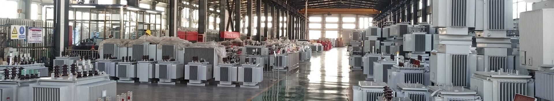
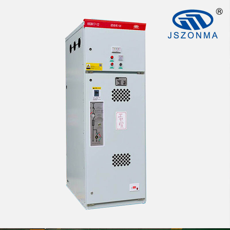
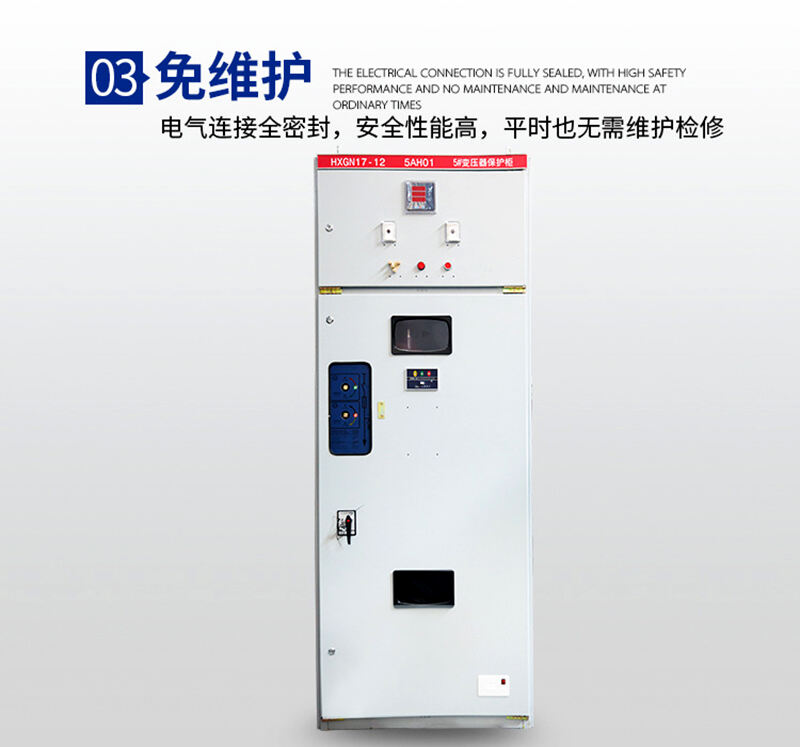

HXGN17-12 AC metal ring main switchgear (referred to as ring main unit) is a new type of high-voltage switchgear produced for the needs of urban power grid renovation and construction. In the power supply system, it is also used for breaking load current, short-circuit current, and closing short-circuit current. This ring main unit is equipped with FN12 and FZRN21 vacuum load switches, and the operating mechanism is a spring mechanism, which can be operated manually or electrically. The grounding switch and isolation knife are equipped with a manual operating mechanism. This ring main unit has strong completeness, small size, no combustion and explosion hazards, and reliable "five prevention" functions. This ring main unit complies with the relevant provisions of GB3906 "3-35kV AC Gold Group Enclosed Switchgear" 1EC60420 "High Voltage AC Load Switch Fuse Combination Apparatus" standard.
Usage conditions
Environmental temperature: upper limit+40 ℃, lower limit -15 ℃
Altitude: not exceeding 1000m; Any place with an altitude exceeding 1000m shall be handled in accordance with JB/Z102-72 "Technical Requirements for High Voltage Electrical Appliances Used in High Altitude Areas".
Relative humidity: daily average not exceeding 95%, monthly average not exceeding 90%
Water vapor pressure: daily average not exceeding 2.2Kpa, monthly average not exceeding 1.8Kpa
Seismic intensity: not exceeding 8 degrees
Usage: No fire, explosion hazard, serious pollution, chemical corrosion, severe vibration, etc
Product Features
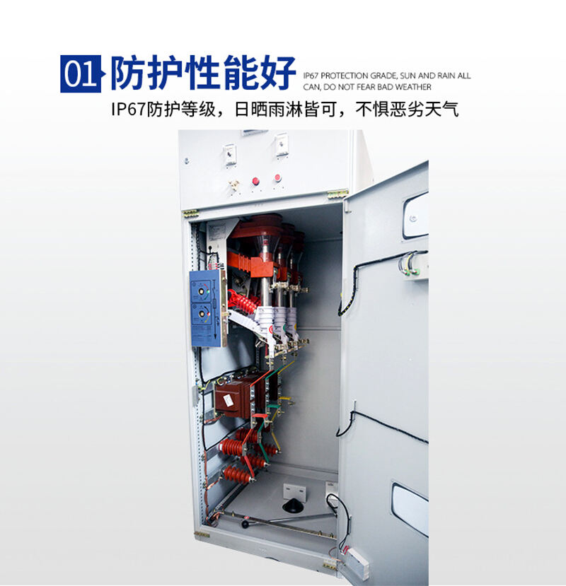
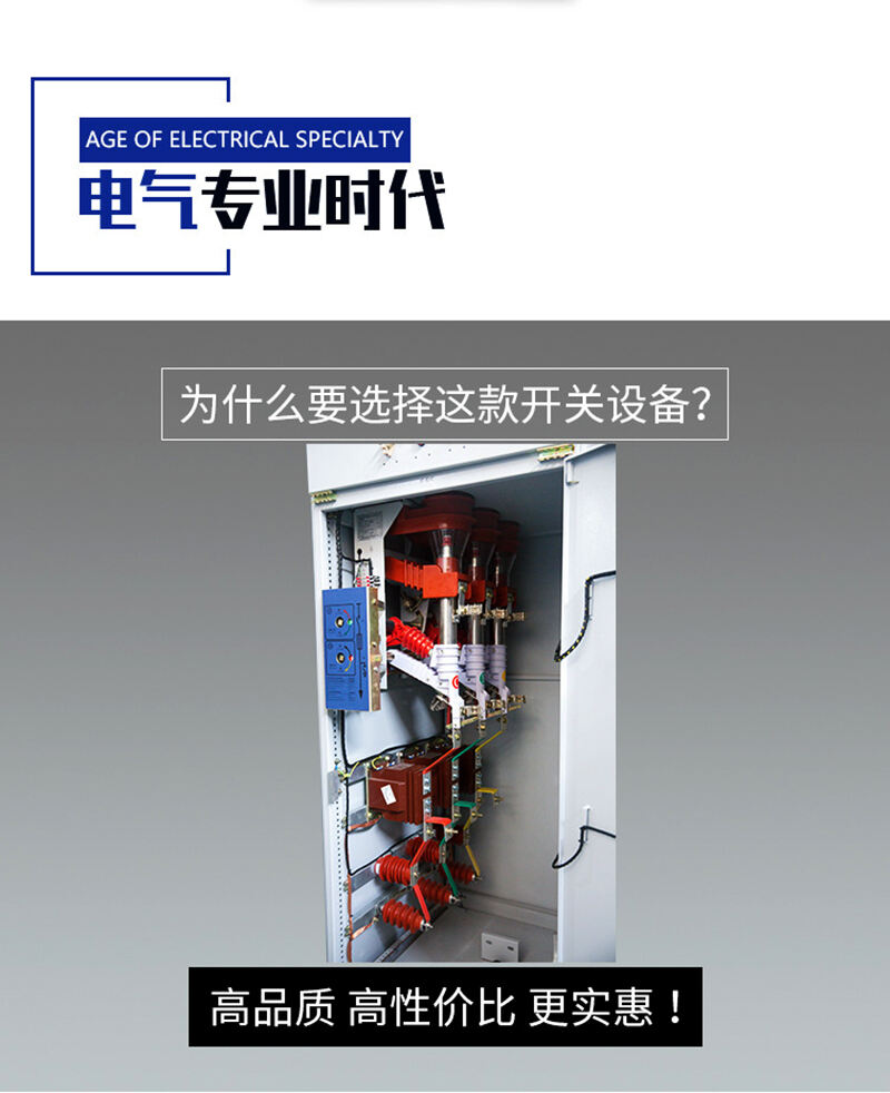
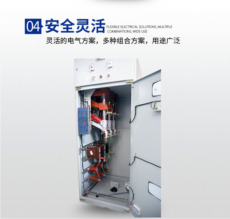
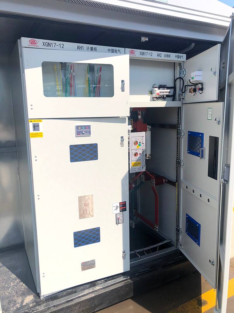
This switchgear is a metal enclosed box structure, and the cabinet body is made of cold-rolled steel plates and angle steel welded together. The color of the cabinet body is specified by the user. Made of useless mesh textiles and non refractory materials. The external insulation creepage distance of each component and supporting insulation in the high-voltage switchgear is ≥ 1.8cm/kV for pure ceramic insulation and ≥ 2.0cm/kV for organic insulation. The air distance between phases and relative ground inside the cabinet is ≥ 125mm. There is an intelligent temperature and humidity controller installed inside the cabinet, which can start and stop the heater at any time according to the temperature and humidity inside the circuit breaker room and cable room to prevent condensation or high temperature. The front of the switchgear is equipped with an observation window, which allows you to observe the on/off positions of the upper and lower isolation switches and circuit breakers without opening the cabinet door.
The switchgear is divided into relay room, circuit breaker room, busbar room, and cable room according to different functions. A small busbar room can be designed on the upper part of the relay room. Rooms are separated by steel plates. And both the circuit breaker room and the cable room are equipped with lighting devices.
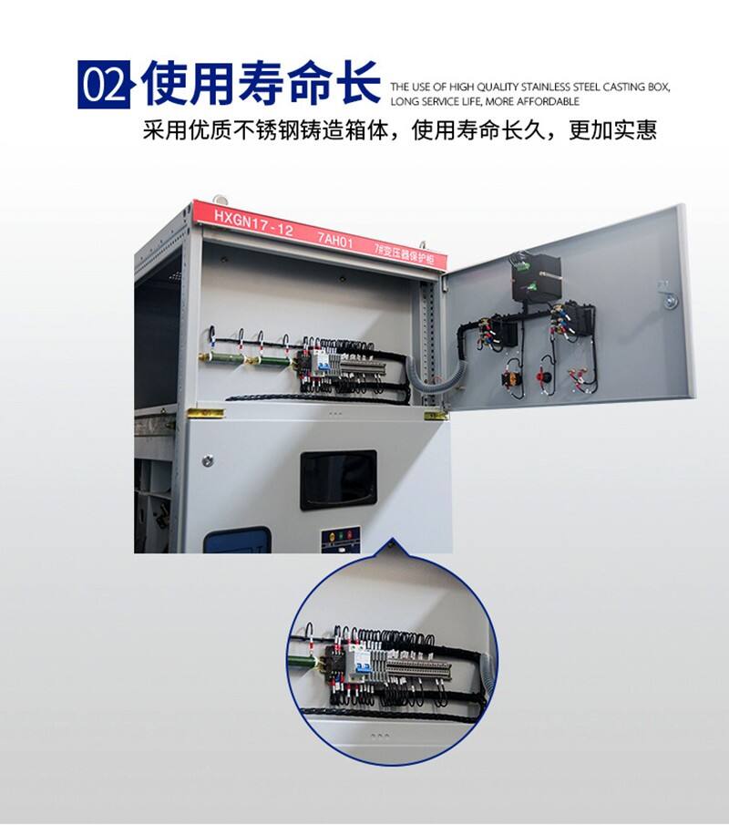
The Switch Cabinet relay room is located on the upper front of the switch cabinet, and all measuring instruments and relay protection devices are installed in this room (including instrument doors). The secondary connection wires of the components are made of 2.5mm2 flame-retardant multi strand copper wires, and the terminal blocks, wiring boards, and fixing screws are all made of copper material. And there are reliable earthquake prevention measures, which will not affect the normal operation and performance of the high-voltage switchgear due to the vibration caused by the normal operation and fault action of the circuit breaker.
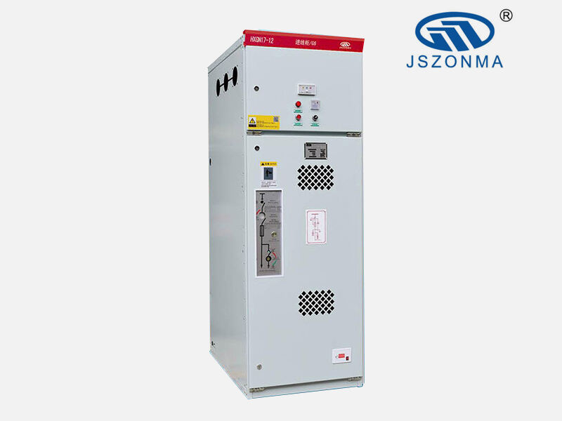
The circuit breaker room is located in the middle of the cabinet, and the transmission of the circuit breaker is connected to the operating mechanism by the pull rod. The lower terminal of the circuit breaker is connected to the upper terminal of the current transformer, and the lower terminal of the current transformer is connected to the terminal of the lower isolation switch. The upper terminal of the circuit breaker is connected to the lower terminal of the upper isolation switch, and there is a position indicator device to correctly indicate the open and close status. There is a pressure release channel at the circuit breaker room, and if an internal arc occurs, the gas can release the pressure through the exhaust channel.
The busbar room is located at the upper rear of the cabinet. In order to reduce the height of the cabinet, the busbars are arranged in a cross shape and supported by ceramic insulators with a bending strength of 7530N. The busbars are connected to the wiring terminals on the upper isolation switch.
The cable room is located behind the lower part of the cabinet, and the supporting insulators in the cable room can be equipped with monitoring devices. The cables are fixed on the brackets. When the main wiring is the interconnection scheme, this room is the interconnection busbar room.
The operating mechanism of the circuit breaker is located on the left side of the front, and above it is the operation and interlocking mechanism of the isolation switch.
Mechanical interlocking: to prevent the opening and closing of isolation switches with load; Prevent accidental opening and closing of circuit breakers; Prevent accidental entry into electrified compartments; Prevent the use of live grounding switches; Prevent closing with grounding knife. The switchgear adopts corresponding mechanical interlocking (i.e. "five prevention" interlocking), and the action procedures of the mechanical interlocking are as follows:
Power outage operation (operation maintenance)
The switchgear is in the working position, that is, the upper and lower isolation switches and circuit breakers are in the closed state, the front and rear doors are closed and locked, and are in live operation. At this time, the small handle is in the working position. Power outage operations must be strictly carried out in the following order:
① Circuit breaker breaking;
② Turn the small handle to the "break lock" position, at which point the circuit breaker cannot be closed;
③ Insert the operating handle into the operating hole of the lower isolation, pull it down from top to bottom, and remove the operating handle after pulling it to the lower isolation opening position;
④ Insert the handle into the upper isolation operation hole and pull it down from top to bottom to the upper isolation disconnection position;
⑤ Remove the operating handle again, insert it into the grounding switch operating hole, and push it from bottom to top to place the grounding switch in the closed position;
⑥ Turn the small handle to the "maintenance" position, open the front door first, take out the program lock key to open the rear door, and complete the power-off operation. Maintenance personnel can perform maintenance and repair on circuit breakers and cable compartments.
Power transmission operation (maintenance operation)
① Close and lock the rear door;
② Remove the key and close the front door;
③ Pull the small handle from the maintenance position to the disconnection locking position, and the front door will be locked at this time;
④ The circuit breaker cannot be closed. Insert the operating handle into the grounding switch operating hole and pull it down from top to bottom to place the grounding switch in the open position;
⑤ Remove the operating handle and insert it into the operating hole of the upper isolation switch. Push it upwards from bottom to make the upper isolation switch in the closed position;
⑥ Remove the operating handle, insert it into the operating hole of the lower isolation, and push it from bottom to top to place the lower isolation in the closed position;
⑦ Take out the operating handle and turn the small handle to the working position. At this point, the circuit breaker can be closed.
There is a grounding copper busbar parallel to the width direction of the cabinet below the front door, with a cross-section of 4 × 40mm2.